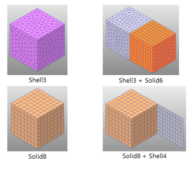
When using the Extrude function in Manual Mesh, based on existing Beam, Shell, Solid mesh, it is possible to generate the new Shell or Solid by selecting face/edge or selecting patch/line set belonging to it as shown in the Figure 1 below.
In addition, RecurDyn/Mesher supports to create a FFlex body with shell and solid together.
Figure 1 The Extrude function in Manual Mesh
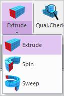
Figure 2 Extrude icon of the Mesher group in the Mesher tab
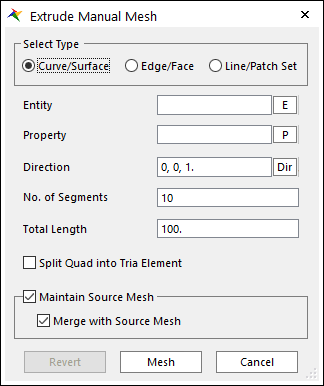
Figure 3 Extrude Manual Mesh dialog box
•Select Type: The type of the source entity to extrude.
•Curve/Surface: Select a curve or surface.
•Edge/Face: Select an edge or face.
•Line/Patch Set: Select a Line Set or Patch Set.
•Entity: Selects the entity that matches the Select Type.
•Property: Selects a proper property. Because you create solid elements from shell elements using this function, it is proper to select solid property regardless of the Type.
•Direction: Defines the direction to extrude.
•No. of Segments: Defines the number of segments to the total length.
•Total Length: Defines the total length of meshed entity.
•Split Quad into Tria Element: Decides to split quad into tria elements.
•Maintain Source Mesh
•If it’s checked, the used source mesh exists after executing manual mesh.
•If it’s unchecked, the used source mesh removed.
•Merge with Source Mesh: Although the source mesh remains after the manual mesh, the result mesh does not share nodes with the source mesh. If this option is checked, the result mesh shares the nodes with the source mesh.
•Revert: Returns the base meshed result.
•Mesh: Executes the mesh. You can see the mesh information such as the number of nodes and elements in Message Window after finishing to mesh geometry.