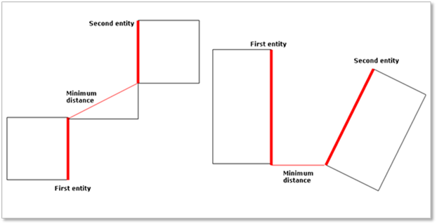
It can be calculated for the minimum distance between two geometries.
Figure 1 Definition of Distance in Edge, Face, Solid Type.
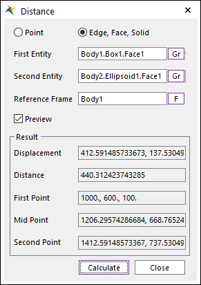
Figure 2 Distance dialog Box [Edge, Face, Solid type]
•Edge, Face, Solid type
•First Entity: Inputs the name of a first entity such as an edge, a face, or a solid geometry to measure the minimum distance.
•Second Entity: Inputs the name of a second entity such as an edge, a face, or a solid geometry to measure the minimum distance.
•Reference Frame: Inputs a reference frame to measure the relative displacement. If the user does not specify it, the default is Inertia Marker of Ground.
•Result
•Displacement: Shows the calculated displacement vector components for the minimum distance between two geometric entities with respect to Reference Frame.
•Distance: Shows the minimum distance between the first entity and second entity.
•First Point: Shows X, Y, and Z position of the start point of the displacement vector with respect to the Reference Frame.
•Mid Point: Shows X, Y, and Z position of the middle point of the displacement vector with respect to the Reference Frame.
•Second Point: Shows X, Y, and Z position of the end point of the displacement vector with respect to the Reference Frame.
•Preview
•Shows First Point, Mid Point and Second Point in the Working Window.
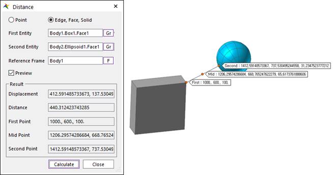
Figure 3 Preview Frist, Mid and Second Point of Distance [Edge, Face, Solid Type]
Step to calculate Distance between two geometries
1. Select Edge, Face, Solid type option.
2. Specify First Entity.
3. Specify Second Entity.
4. Specify Reference Frame.
5. Click Calculate.