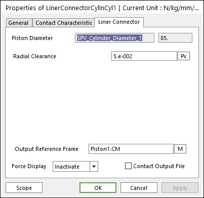
Figure 1 Liner Connector property page [Cylinder In Cylinder Contact]
•Output Reference Frame: The user can choose another desired Reference Marker.
•Contact Output File: If it is checked, the user can get specific output information file such as:
|
Variables |
Descriptions | |
|
1 |
Time(sec) |
Simulation Time |
|
2 |
amount of contact point |
Total number of calculated contact points |
|
3 |
Pos_TX of Base Body CM |
Position X of Center Marker for Base Body from Global |
|
4 |
Pos_TY of Base Body CM |
Position Y of Center Marker for Base Body from Global |
|
5 |
Pos_TZ of Base Body CM |
Position Z of Center Marker for Base Body from Global |
|
6 |
Pos_PSI of Base Body CM |
Position of Center Marker for Base Body in 3-1-3 Euler angle from Global |
|
7 |
Pos_THETA of Base Body CM |
Position of Center Marker for Base Body in 3-1-3 Euler angle from Global |
|
8 |
Pos_PHI of Base Body CM |
Position of Center Marker for Base Body in 3-1-3 Euler angle from Global |
|
9 |
Pos_TX of Action Body CM |
Position X of Center Marker for Action Body from Global |
|
10 |
Pos_TY of Action Body CM |
Position Y of Center Marker for Action Body from Global |
|
11 |
Pos_TZ of Action Body CM |
Position Z of Center Marker for Action Body from Global |
|
12 |
Pos_PSI of Action Body CM |
Position z-axis of Center Marker for Action Body in 3-1-3 Euler angle from Global |
|
13 |
Pos_THETA of Action Body CM |
Position x-axis angle of Center Marker for Action Body in 3-1-3 Euler angle from Global |
|
14 |
Pos_PHI of Action Body CM |
Position z-axis of Center Marker for Action Body in 3-1-3 Euler angle from Global |
|
15 |
Global contact position |
Position of Contact Points from Global |
|
16 |
Contact position based on Base Body |
Position of Contact Points from Base Body |
|
17 |
Contact position based on Action Body |
Position of Contact Points from Action Body |
|
18 |
Contact force based on Action Body |
Contact Force from Action Body |
|
19 |
Friction force based on Action Body |
Friction Force from Action Body |
The user can see the output file in your working folder where your model is in. The output file name is ‘Filename_ContactElementName.out’.
•Radial Clearance: Defines as a gap between the cylinder and piston.
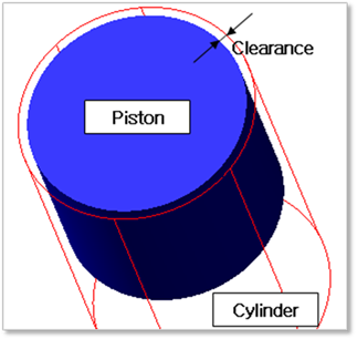
Figure 2 Definition of Clearance
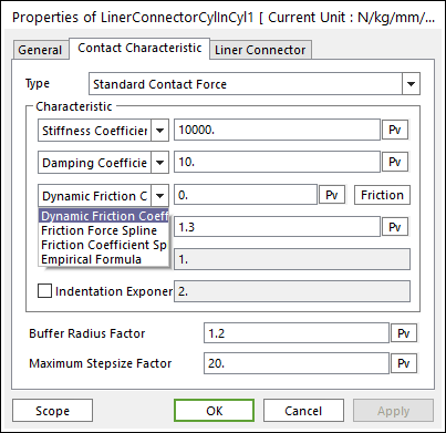
Figure 3 Contact Characteristic dialog box [Cylinder In Cylinder Contact]
•Please refer to Type of Friction in below.
•Standard Friction
① Select Friction Coefficient in the combo box.
② Click More and then values to define Coulomb Friction. For more information, refer to click here.
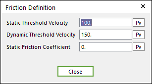
Figure 4 Friction Definition dialog box
•Empirical Formula (Refer to Constraint Bearing)
① Select Empirical formula in the combo box.
② Click More and enter the values to define Empirical Formula Friction. For more information, click here.
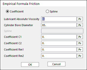
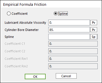
Figure 5 Empirical Formula Friction dialog box