During the course of engagement between the sprocket teeth and the track links, several sprocket teeth can be in contact with several track links pins, as shown in Figure 1. A Cartesian coordinate system is introduced for each contact surface. The surface coordinate system is assumed to have a constant orientation with respect to a selected tooth coordinate system. The tooth coordinate system has a constant orientation with respect to the coordinate system of the sprocket. Therefore, the orientation of a surface coordinate system can be defined in the global system using three coordinate transformation matrices; two of them are constant and the third is the time dependent rotation matrix of the sprocket. Using these coordinate transformations and the absolute Cartesian coordinates of the origin of the sprocket coordinate system, the location and orientation of each tooth surface can be defined in the global coordinate system. Using the track link coordinate system, the global position vector of the center of the track link pin can be defined. This vector and the global coordinates of the tooth surfaces can be used to determine the position of the track link pins with respect to the sprocket teeth. The relative position of the track link pins, with respect to the sprocket teeth can be used to develop a computer algorithm that determines whether or not the track link pin is in contact with one of surfaces of the sprocket teeth.
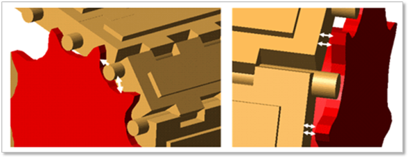
(a) Sprocket teeth and pin contact (b) Teeth side wall and link side wall contact
Figure 1 Sprocket tooth and track interactions