
This section explains how to build FE model and analyze it with CMS method in Workbench.
The example model is 2D rectangular model.
1. Select Modal analysis in Analysis Systems.
Figure 1 Modal analysis system
2. Create a geometry for FE model.
•Enter DesignModeler program in the popup menu on Geometry.
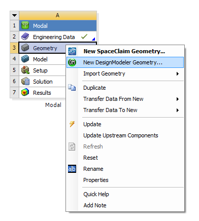
Figure 2 Popup Menu on Geometry
•Create a rectangle geometry in DesignModeler.
① Create a skech on XY Plane.
② Create a surface from the skech by using Surfaces From Skeches
③ Generate the geometry by using Generate.
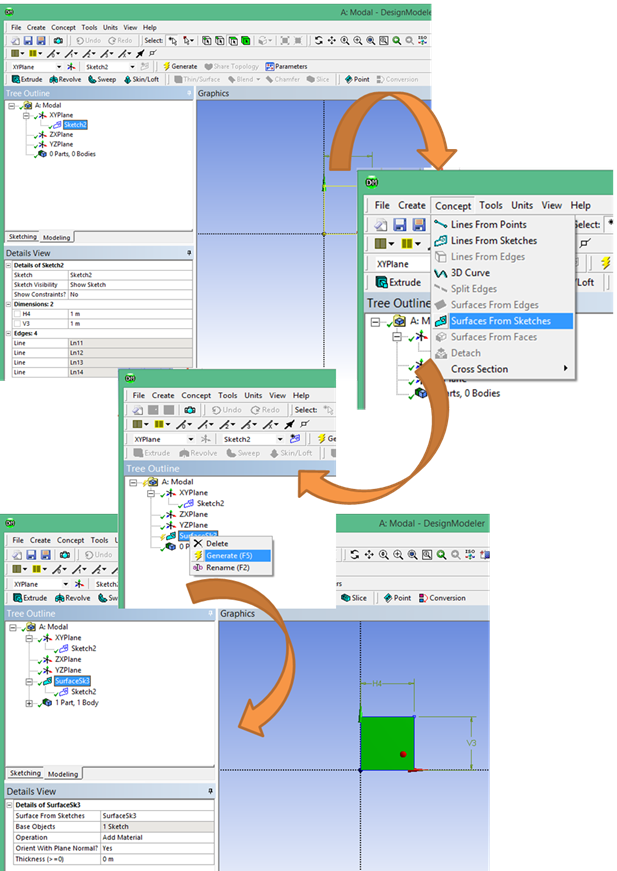
Figure 3 DesignModeler
3. Create a FE model and Analsyis.
•Enter Edit… on the popup menu on Model.
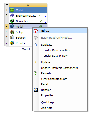
Figure 4 Popup Menu on Model
•Define the thickness of the surface geometry as 0.05.
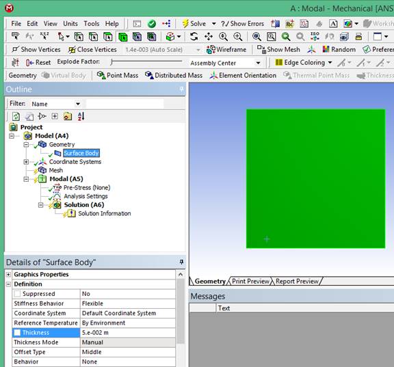
Figure 5 Setting the thickness
•Mesh the surface geometry.
① Set the element size as 0.1 by using Body Sizing.
② Set the mesh type as all quad in Automatic Method.
③ Mesh with Generate Mesh.
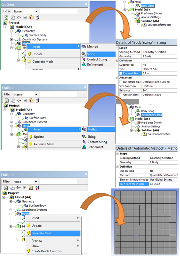
Figure 6 Mesh the surface geometry
4. Define interface nodes.
•Create a Remote Point to define interface nodes.
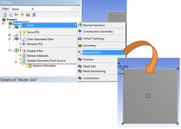
Figure 7 Setting Remote Point
•Insert a Command to define the name for the remote point.
“MASTER_1=_npilot”
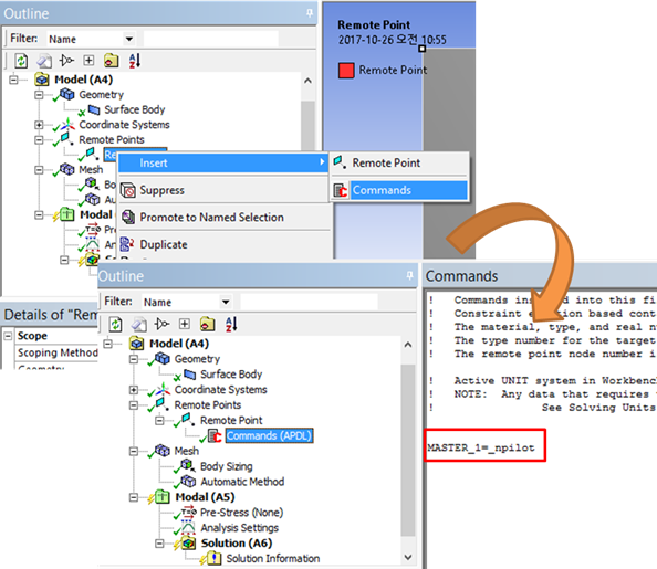
Figure 8 Command for Remote Point
5. Solve Modal Analysis
•Insert a Command for CMS analysis.
① In command, it is necessary to have macro input file contents provided by RecurDyn. The file is in <Install Dir>\Toolkits\Flexible input files\ANSYS folder.
② Additionally, NMODES and CM parameters should be inputted.
“NMODES=10”
“nsel,s,,,MASTER_1”
“CM,INTERFACE,node”
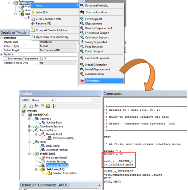
Figure 9 Command for CMS analysis
•Define Analysis Settings
•In order to include strain shape and stress shape, check Output Controls.
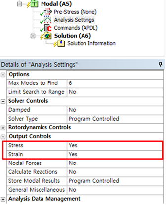
Figure 10 Output Controls
•Solve
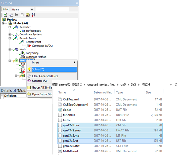
Figure 11 Result files