
This section explains how to build FE model and analyze it with CMS method.
The example model is 2D rectangular model. The model can be meshed as shell 63 element with Element edge length option. Shell 63 elements have Real Constant with thickness, 0.05. Steel material is used in this model.
Figure 1 Target model
1. Select Mechanical APDL Product Launcher on the popup menu and specify working directory and job name.
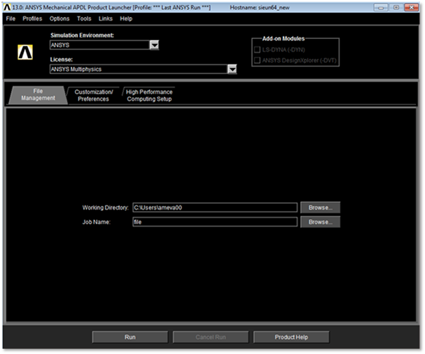
Figure 2 ANSYS launcher
2. Select Structural on the Preferences for GUI filtering
•Preferences for GUI filtering
•Preferences > Structural
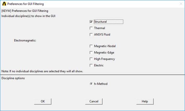
Figure 3 Preference for GUI filtering
3. Select Element Type, Real Constants
•Element type
•Preprocessor > Element Type > Add/Edit/Delete > Add… > Shell 63 > OK > Close
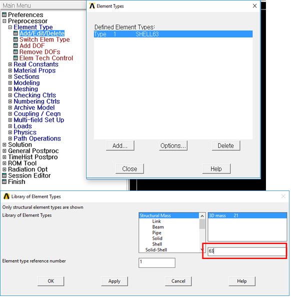
Figure 4 Set Element Type
•Enter Real Constants
•Preprocessor > Real Constants > Add/Edit/Delete > Add > OK
•Set shell thicknesses I, J, K, L as 0.05
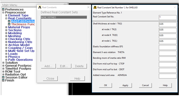
Figure 5 Real constant for shell element
3-1. Set Thickness
•Thickness
•Thickness is important parameter for shell element. Ansys do not support
Real Constant for some shell element.
At the time, thickness can be define
using shell section.
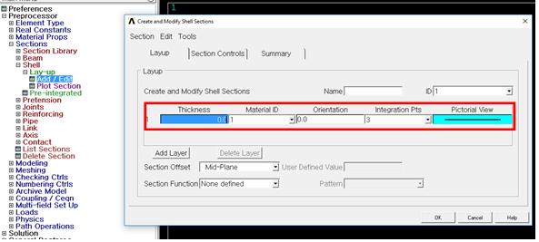
Figure 6 Create Sections for Shell Element
4. Enter Material property
•Material property
•Preprocessor > Material Props > Material Models > Structural > Linear > Elastic > Isotropic > Specify material number as 1 > OK
•Fill in the Young’s modulus(70e9N/m2), Possion ratio(0.33), density(2710kg/m3) > OK
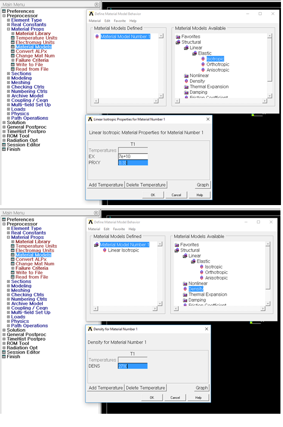
Figure 7 Material Property
5. Create rectangular geometric entity
•Create Rectangle by Dimensions
•Preprocessor > Modeling > Create > Areas > Rectangle > By Dimensions > OK
•Fill the x1, x2, y1, & y2 as 0.0, 0.0, 1.0, & 1.0 > OK
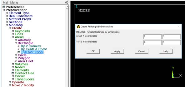 |
Figure 8 Rectangle by Dimensions
6. Create area meshing using Mesh Tools
•Use line set to define element edge length.
•Preprocessor > Meshing > MeshTool > Size Controls > Lines > Pick All > OK > SIZE element edge length(0.1) > OK
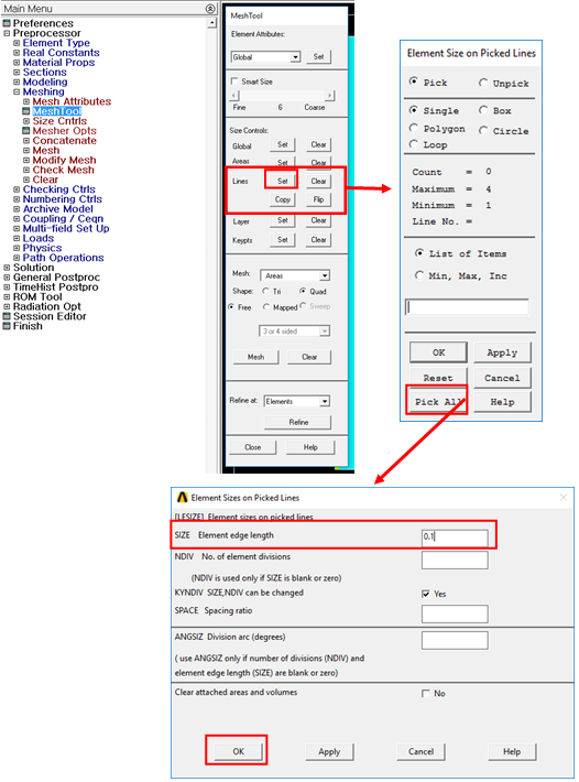
Figure 9 Line set with Element edge length
•Mesh model
•Mesh Tool > Mesh > Select model > OK
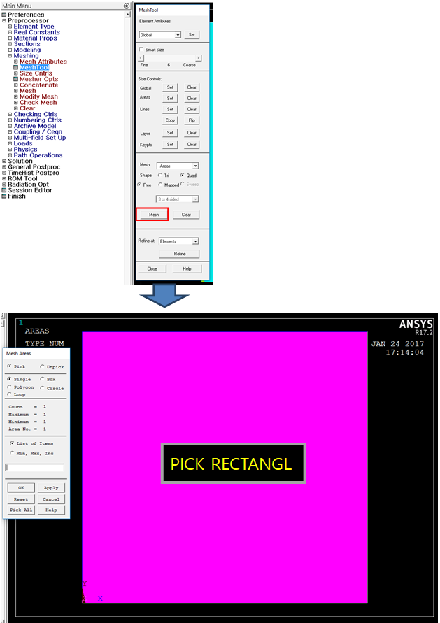
Figure 10 Meshed Rectangular geometric entity
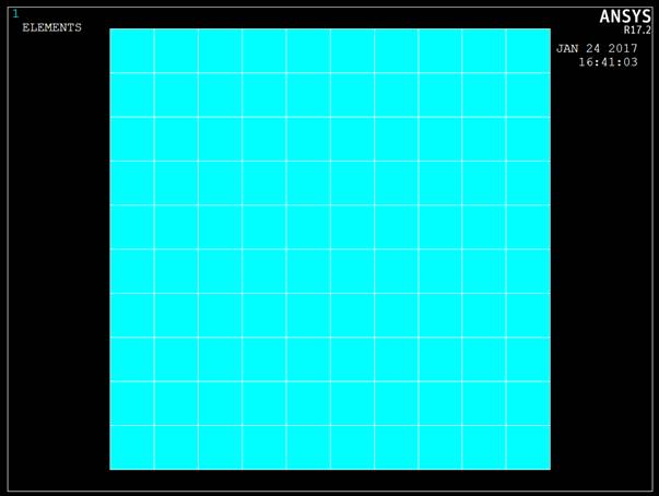 |
Figure 11 Mesh Result
7. Define Interface nodes
•Select> Component Manager
•Create Component
•Create from 'Nodes'
•Check 'Pick entities'
•Name new component 'INTERFACE'
•Select interface nodes on FE model
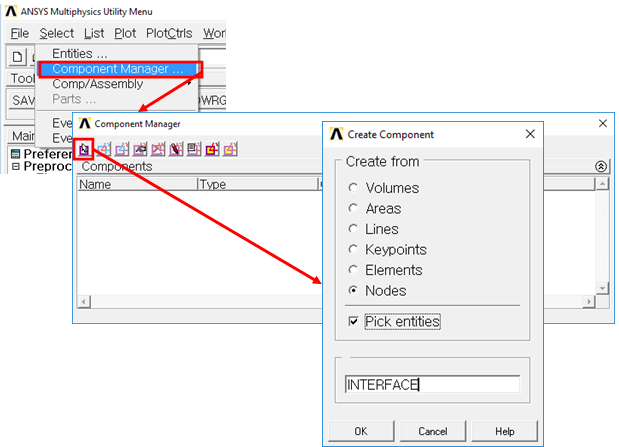
Figure 12 Create new component
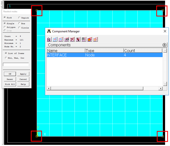
Figure 13 Select Interface nodes
8. Define Parameter
•Parameters> Scalar Parameters
•Input the number of modes like 'NMODES=10'
•Accept it
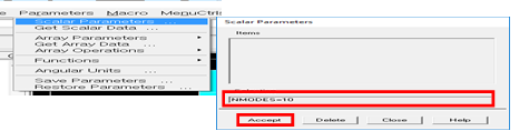
Figure 14 Set the number of modes
9. Read RecurDyn's input file for CMS analysis
•File> Read Input from
•Read 'RecurDyn_AnsysCMS.MAC'
•This macro input file is included in the following folder.
o '<Install Dir>\Toolkits\Flexible input files\ANSYS'

Figure 15 Created files
10. Check the result files.
11. The four files must exist in work folder.
•genCMS.rst
•genCMS.mp
•genCMS.emat
•genCMS.cm
Caution!
•The user can perform the CMS(Component Mode Synthesis) analysis in ANSYS. CMS allows the user to derive the normal modes and static correction modes at once from ANSYS. It is difficult to perform CMS analysis by the provided steps of ANSYS. So, it is strongly recommended that the user performs CMS analysis with the provided macro file (RecurDyn_AnsysCMS.MAC). This macro file is included in “<Install Dir>\Toolkits\Flexible input files\ANSYS\ RecurDyn_AnsysCMS.MAC”.
•If ANSYS does not generate the element matrices file automatically, use the EMATWRITE command. If the user uses the macro file, this command is not needed.
•If ANSYS does not generate the file included in material information automatically, the user should type the MPWRITE command in the solution menu. If the user uses the macro file, this command is not needed.
Note
The sample model is supported in <Install Dir>/Toolkits/Flexible input files/ANSYS directory.