
In the bushing force model for single pin track, a compliant force model is used to define the pin joint connections. This force model is a non-linear function of the coordinates of the two links. In order to define the generalized compliant bushing forces, several coordinate systems are introduced. Two centroidal body coordinate systems for the track links i and j, a joint coordinate systems origin is assumed to be located at the geometric center of the circular groove containing the pin and the bushing for track link i, and a pin coordinate system for track link j whose origin is rigidly attached to the center of the pin. Note that because of the bushing effect, the origins of the joint and pin coordinate systems do not always coincide. The displacement of the pin coordinate system with respect to the joint coordinate system is a function of the bushing stiffness. Also note that the location and orientation of the joint coordinate system can be determined as a function of the generalized coordinates of link i. For simplicity, it is assumed in this bushing force model that the location and orientation of the pin coordinate system can be defined in terms of the coordinates of link j. The radial spring provides the restoring force due to the combined translational deformation of the rubber bushings on XY plane direction as shown in Figure 1. The axial spring restricts the translational motion of the two links along the lateral direction as shown in Figure 1. The rotational springs are used to model the relative rotational deformation between the two track links.
The magnitude of the force produced by the radial spring is
where,  is the spring stiffness
coefficient, and
is the spring stiffness
coefficient, and  is the damping coefficient.
Similarly, the restoring force due to the translational spring along the Z axis
is
is the damping coefficient.
Similarly, the restoring force due to the translational spring along the Z axis
is

where,  is translational deformation of the
pin coordinate systems of body j with respect to the pin coordinate systems of
body i along the Z axis,
is translational deformation of the
pin coordinate systems of body j with respect to the pin coordinate systems of
body i along the Z axis,  and
and  are the
stiffness and damping coefficients. The torque as the result of the relative
rotation of link j with respect to link i are given by
are the
stiffness and damping coefficients. The torque as the result of the relative
rotation of link j with respect to link i are given by

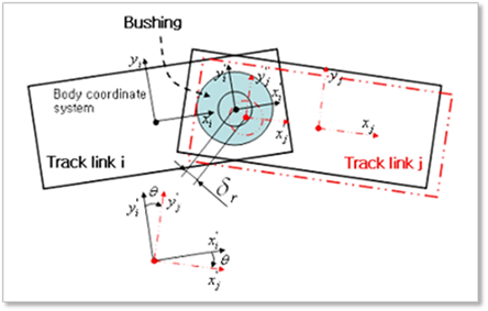
Figure 1 Bushing force model for single pin link