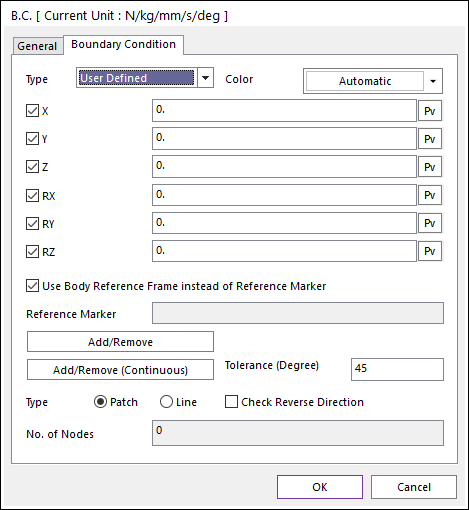
Figure 1 Boundary Condition dialog box
•Boundary Condition Type: Defines a type of boundary condition.
•The default is User Defined, where you can select the DOFs yourself.
•The other type includes options such as Clamped and Simply Supported, where the DOFs are already selected for you.
•Color: The boundary condition is displayed with this color.
•Use Body Reference Frame instead of Reference Marker: Uses the body reference frame instead of the reference marker.
•Reference Marker: Defines the reference maker by clicking M. It is activated when the Use Body Reference Frame instead of Reference Marker option is unchecked.
•Add/Remove: Selects nodes to add or remove for a boundary condition.
•Add/Remove (Continuous): Select a patch or line to add or remove continuously with its own patch or line continuity in angle tolerance for a boundary condition.
•Tolerance (Degree): Defines an angle tolerance to check patch or line continuity.
•Check Reverse Direction: If this option is checked, nodes are selected regardless to direction of patches or lines in the angle tolerance.
•Type Patch: Select a patch then continuously connected patches are added, and the nodes of the patches are selected.
•Type Line: Select a line then continuously connected lines are added, and the nodes of the lines are selected.
•No. of Nodes: Shows the number of nodes included in the BC.