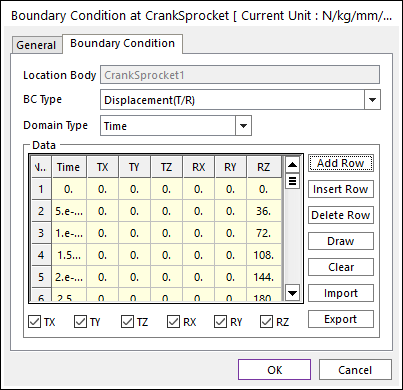
Click Input of Boundary Condition in the Component Builder dialog box. And then the following dialog box can appear.

Figure 1 Boundary Condition dialog box
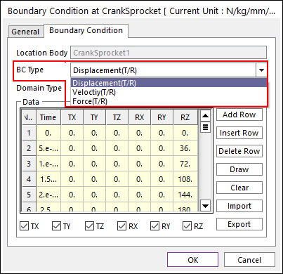
1. Selecting BC Type, the user can define the kinds of boundary condition for Y-axis.

Figure 2 Selecting BC Type
2. Selecting Domain Type, the user can define the domain of boundary condition for X-axis.

Figure 3 Selecting Domain Type
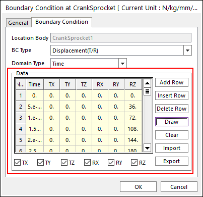
3. Clicking the Add Row, Insert Row and Delete Row, the user can edit the data.
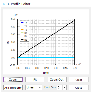
4. Clicking Draw, the user can confirm the profile of boundary condition as follows.

Figure 4 BC Profile Editor
5. The user can mark the boxes to apply desired boundary conditions as follows.

Figure 5 Applying Boundary Condition