Additional Mesh Options are supported in AutoMesh. Additional Mesh Options provide variety of shell and solid mesh options.
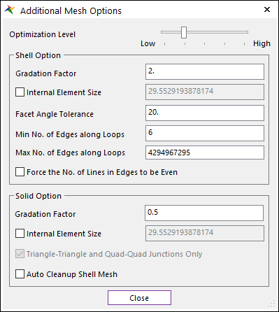
Figure 1 Additional Mesh Options dialog box
•Optimization Level: When the closer the slider position located at Low, meshing speed is maximal, but the quality may be poor. When slider is located at default position, Optimization is usually a good trade-off between quality and speed. the closer the slider are located at High, the better Element of Shape and size quality.
•Shell Option: The below functions support only for Shell element.
•Gradation Factor: You can set the gradation factor. The gradation factor adjusts the gradation of the elements size between the Min Element Size towards to the Max Element Size. This value close to 0 leads to a more progressive variation of mesh size. (Shell Default = 2, Solid Default = 0.5)
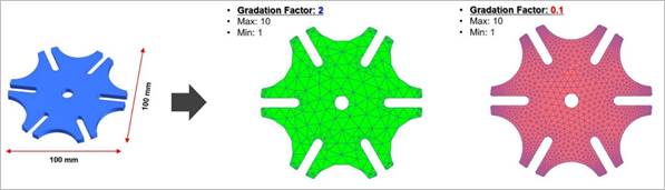
Figure 2 Definition for Gradation Factor
•Internal Element Size: The elements size tends (according to gradation factor parameter) toward this value as they get away from the edge of patch lines.
•Facet Angle Tolerance: If the angle of an adjacent initial facet is greater than the value, it is defined as the edge of the facet. A small value tends to give numerous small facets and the final mesh will be close to the initial mesh but may be of poor quality. A big value tends to give fewer bigger facets.
•Min/Max No. of Edges along Loops: This parameter defines the minimum/maximum number of edges when meshing holes or loops. This parameter works only for shell mesh.
•Force the No. of Lines in Edges to be Even: Flag forces the number of lines in the edge of patch to be even.
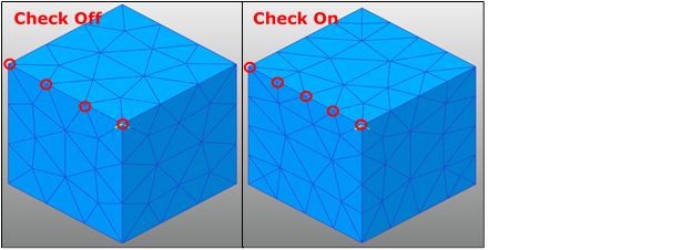
Figure 3 Example of Force the No. of Lines in Edges to be Even applied to the mesh
•Solid Option: The below functions support only for Solid element.
•Internal Element Size: The elements size tends (according to gradation factor parameter) toward this value as they get away from the boundary faces.
•Triangle-Triangle and Quad-Quad Junction Only: This flag allows the internal patches to be shared only if the two patches type match exactly. If set to true, only triangle-triangle and quad-quad junctions are allowed. This usually leads to more nodes, more Solid4, 5 (tet, pyramid) and fewer Solid6, 8 (wedge, hex). If set to false, Solid8(hex) for instance can be joined by one of its face to two tetrahedrons (quad – triangle junction).
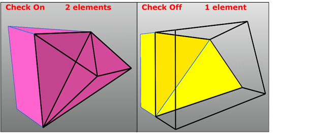
Figure 4 Example of Tri-Tri and Quad-Quad Junction Only applied to the mesh
•Auto Cleanup Shell Mesh: When the parameter is set to true, if solid mesh fails, the shell mesh is remeshed by modified some options automatically first. Then solid mesh is retried through the modified shell mesh. However, setting to true does not always guarantee the success of the failed case.